Structure
The objective of this project is to introduce an elementary understanding of
structure and construction principles through research, design and
production of a full size 3D structure.
structure and construction principles through research, design and
production of a full size 3D structure.
The project is initially focus on research into existing structures and
through the detailed study of specific structure types a knowledge base will
be formed to draw on in the subsequent design exercise.
through the detailed study of specific structure types a knowledge base will
be formed to draw on in the subsequent design exercise.
The project is divided into the following four parts:
- PART ONE/ WEEK 1: Research
- PART TWO/ WEEK 2: Design Development
- PART THREE/ WEEKS 3-4: Final Design & Production information
- PART FOUR/ WEEKS 5-7: Fabrication, Test Assembly & Installation
PART ONE/ WEEK 1: Research - Individual work
Part One was largely introductory and concentrate on three categories of research;
- WALLS/COLUMNS,
- FLOORS
- ROOFS.
I was asked to study the following structure type:
STEEL FRAME-WALLS/COLUMNS
including truss, space frame,lattice grids & beams
STEEL FRAME-WALLS/COLUMNS
including truss, space frame,lattice grids & beams
I was required to present techniques of construction and basic structural principles in five existing structures.
I chose the following structures:
I chose the following structures:
- Bridge 5721 in Minnesota
- Robert Schroeder`s bridge in California.
- Capital gate tower in Abu Dhabi
- CCTV building in Beijing
- Hotel Burj Al Arab in Dubai
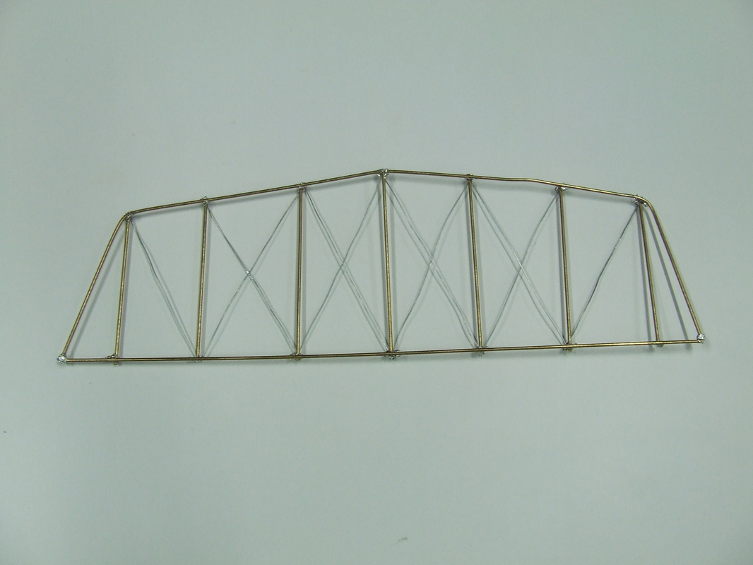
Bridge 5721 in Minnesota
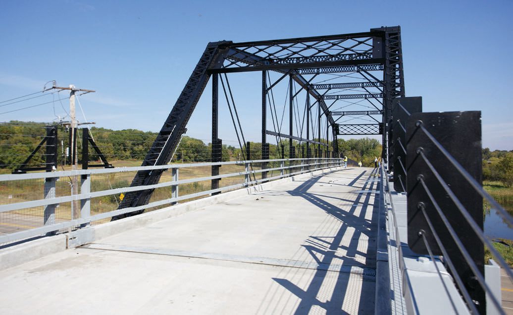
The architect is Robert Schroder.Bridge named 5721 live third life to the third place after a detailed inspection, disassembly, repair and reassembly of the new location. In its original form the facility was built around 1870. Constructive bridge is 50 meters with a hole in one hole.
The main support system consists of farms with grid "Parker" and joints:
-8 vertical supporting roadway width 5.20 m
- diagonal elements operating strength
-outlined curved upper belt
The main support system consists of farms with grid "Parker" and joints:
-8 vertical supporting roadway width 5.20 m
- diagonal elements operating strength
-outlined curved upper belt
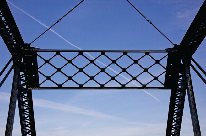
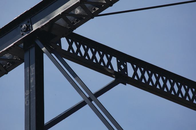
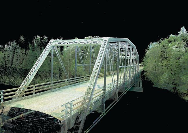
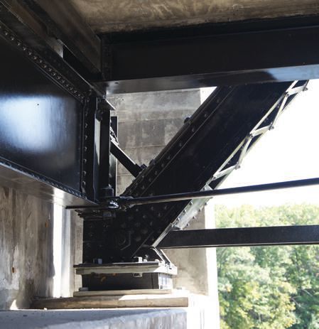
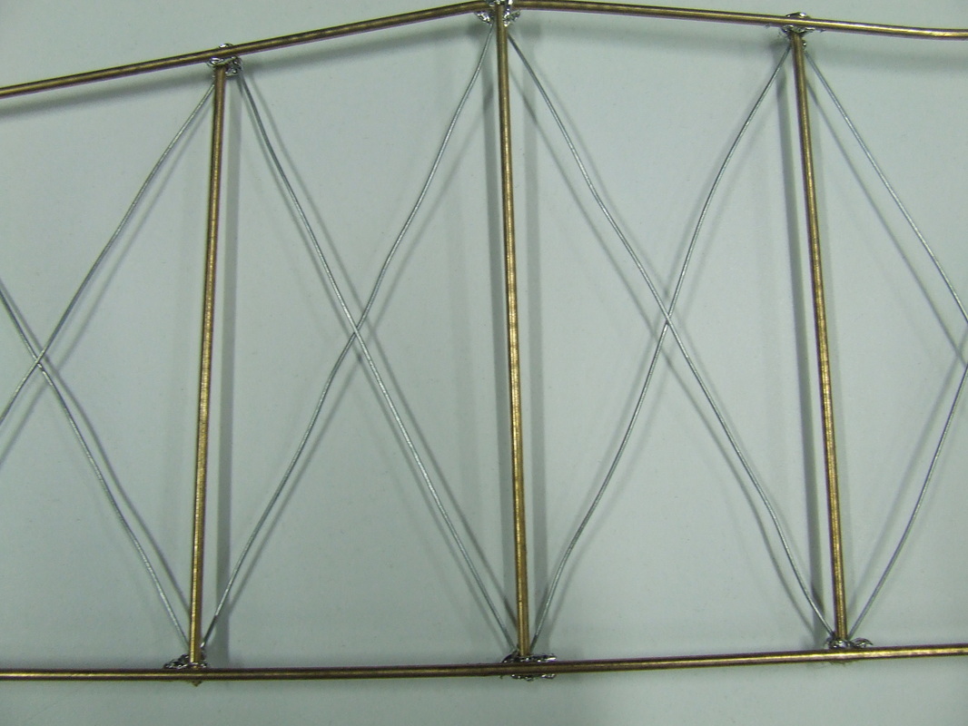
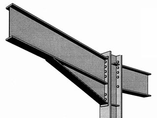
The bottom of the beam experiences the most tension and the top of the beam gets the most of the compression.There is little compression and tension in the middle. There are I-beams, which provide more material on the tops and bottoms of beams to better
handle the forces of compression and tension.
Reference: http://smartbeams.wordpress.com
Reference: http://smartbeams.wordpress.com
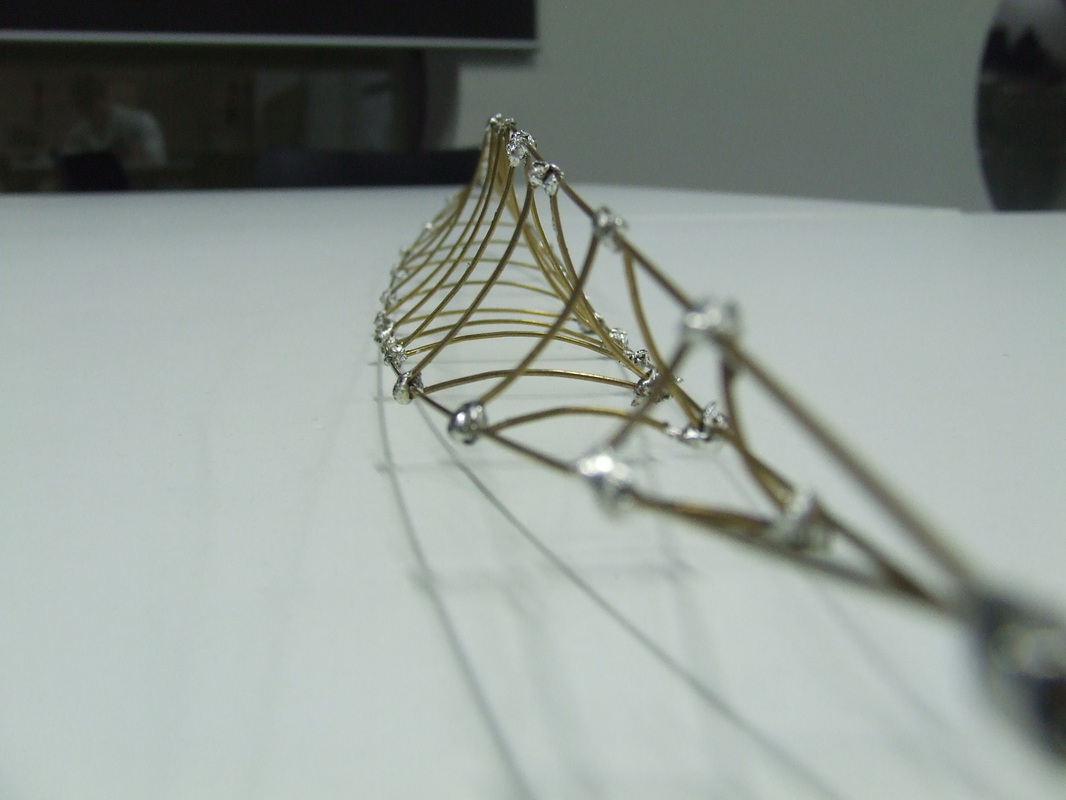
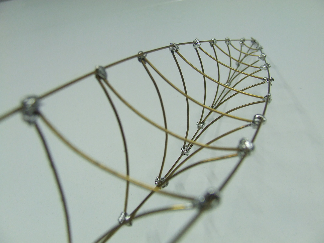
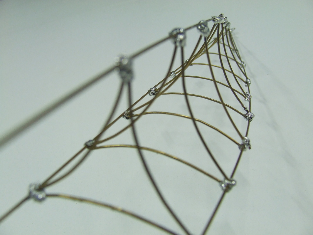
Photos of physical model
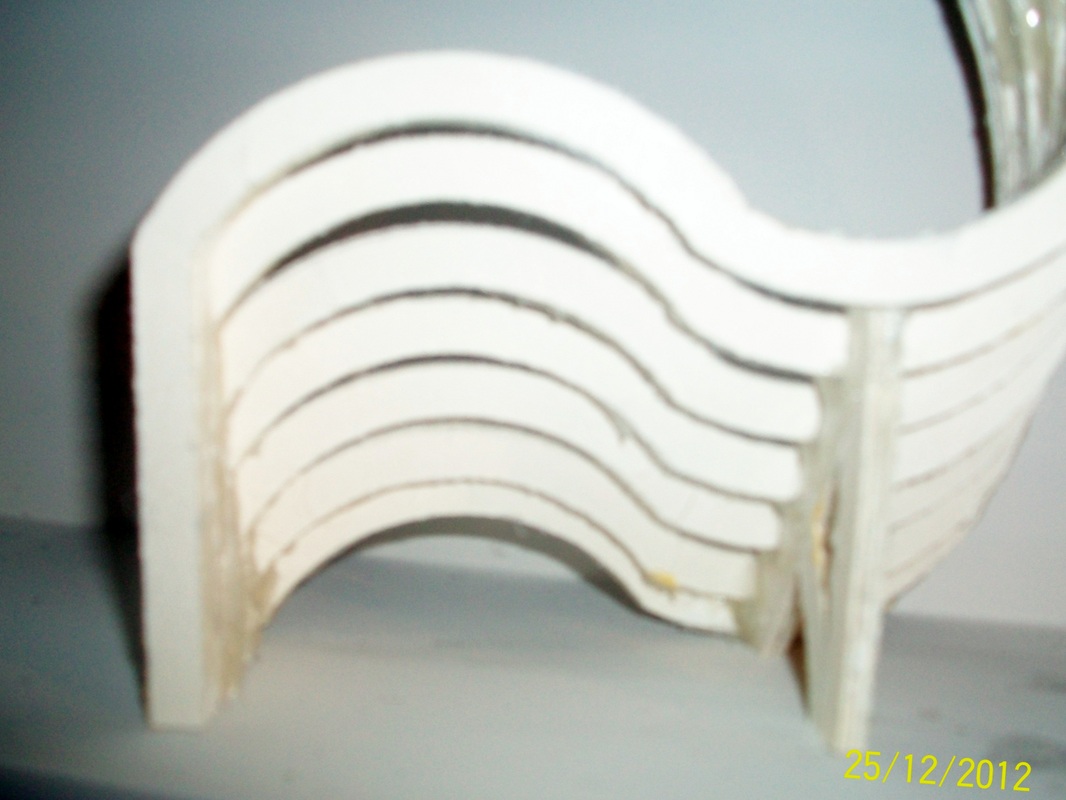
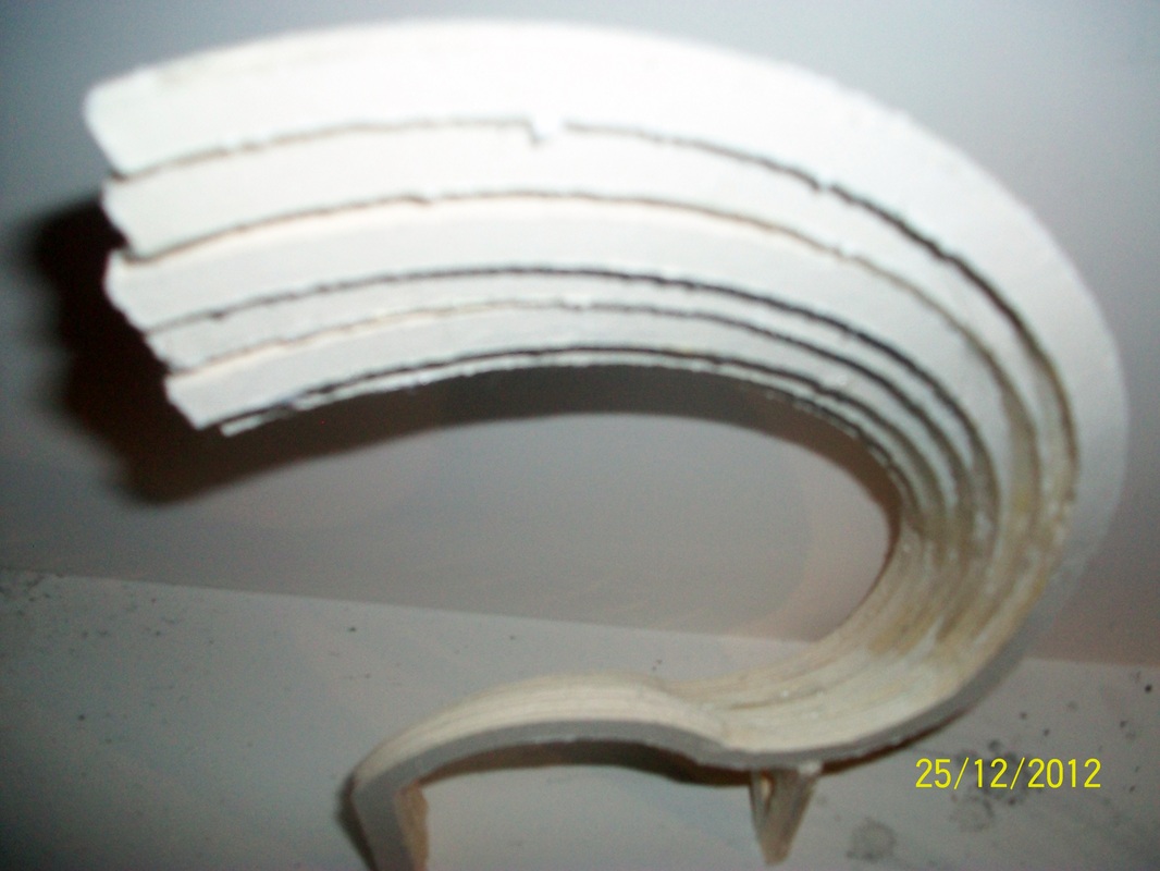
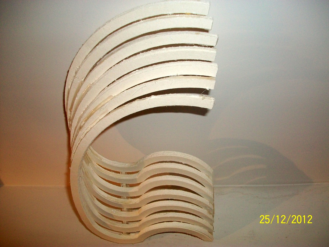
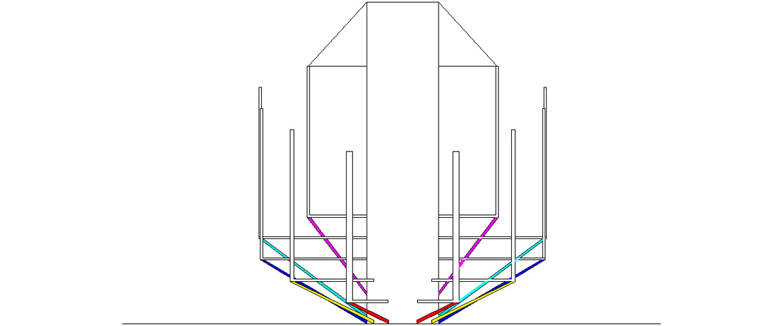
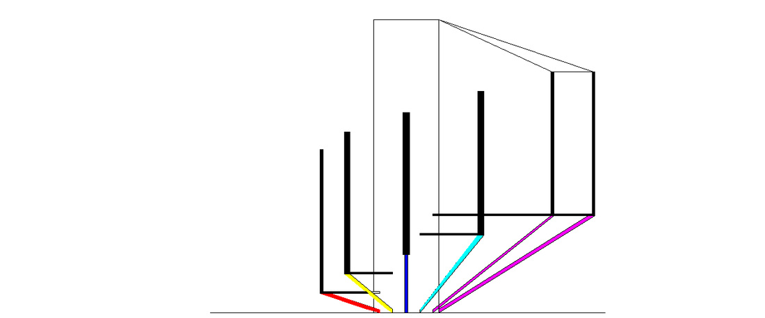
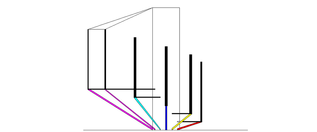
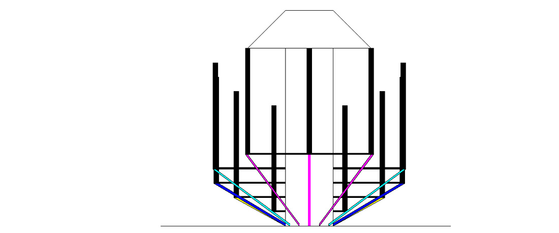
Robert Schroeder`s bridge in California
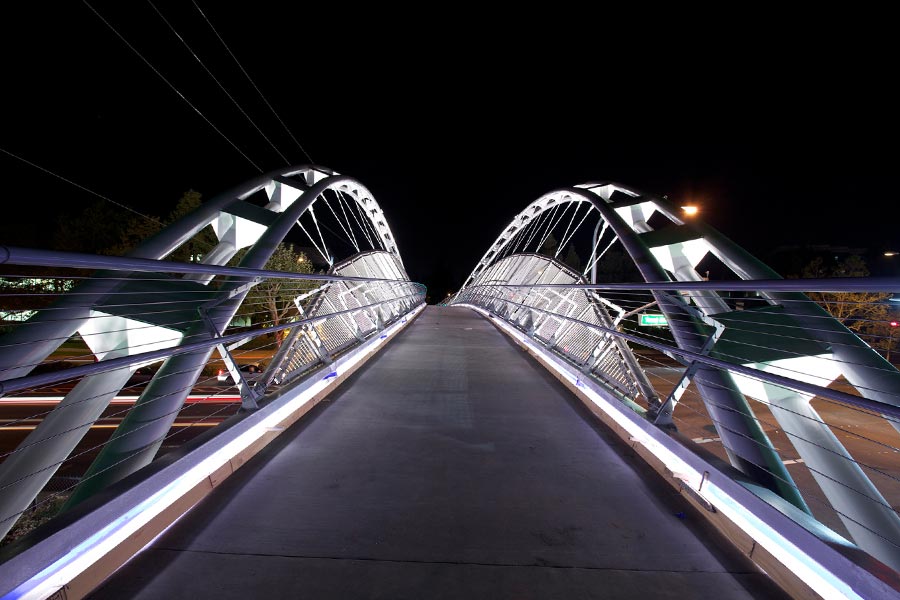
This bridge was built in 2010 in California.
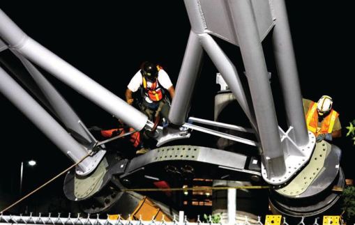
Conditions require a narrow foundation. The solution: two inclined arches convert in one place, providing a narrow and deep foundations.Arches themselves are composed of 3-section tubes with a diameter of 25 cm, together with connecting plates. Bracing between the arches is realized below the horizontal road construction through the box girder in reinforced concrete foundations, leaving 3/4 of the length of the arch free of reinforcements.
Conditions require a narrow foundation. The solution: two inclined arches convert in one place, providing a narrow and deep foundations.Arches themselves are composed of 3-section tubes with a diameter of 25 cm, together with connecting plates. Bracing between the arches is realized below the horizontal road construction through the box girder in reinforced concrete foundations, leaving 3/4 of the length of the arch free of reinforcements.
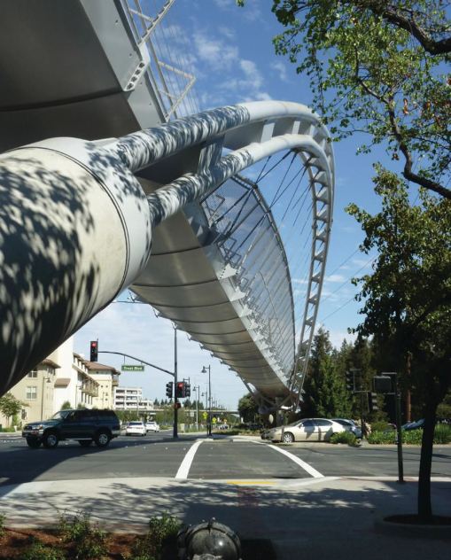
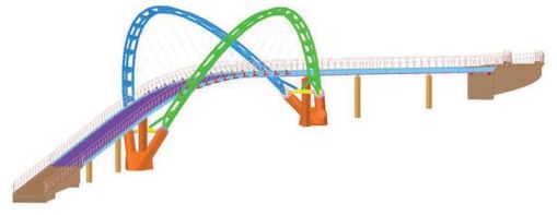
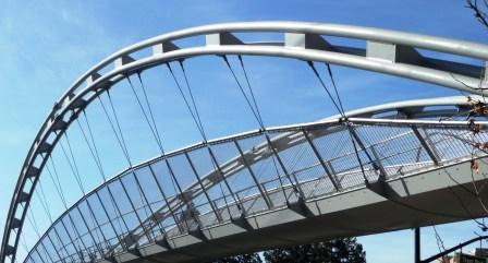
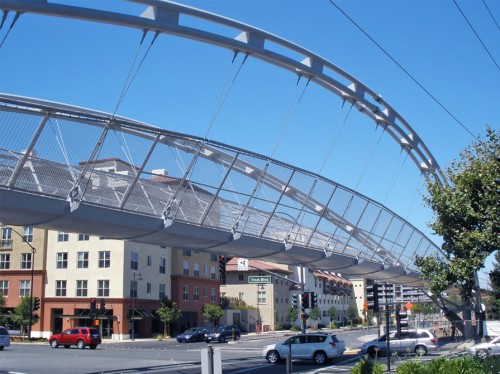
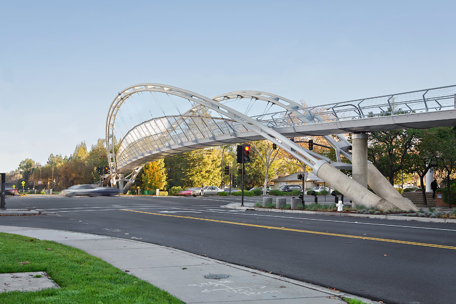
Road construction is based on the arches by ropes down from the arch of 24 seats. Ropes are double, sloping and intersect the "X" for greater stability. They divided arches by 2 parts of 20 tones.And the hole construction has been finished for 3 days. One of the arches, one for road construction and one for settings and installation of rope fence.
Reference: http://smartbeams.wordpress.com
Reference: http://smartbeams.wordpress.com
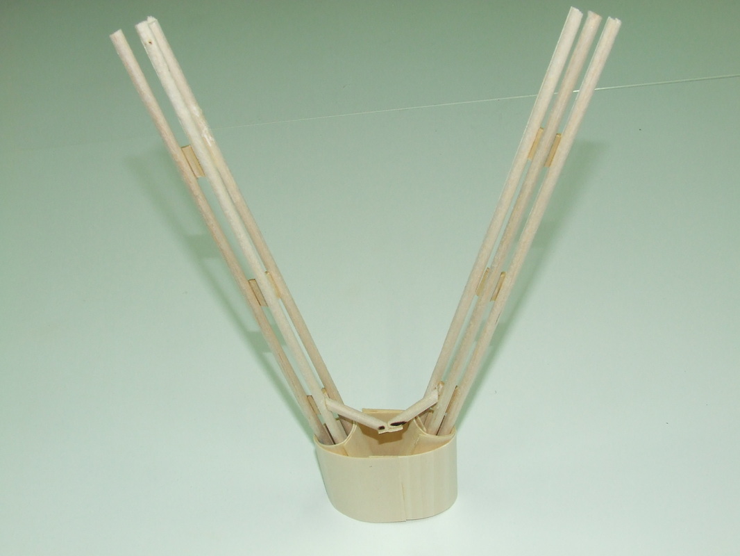
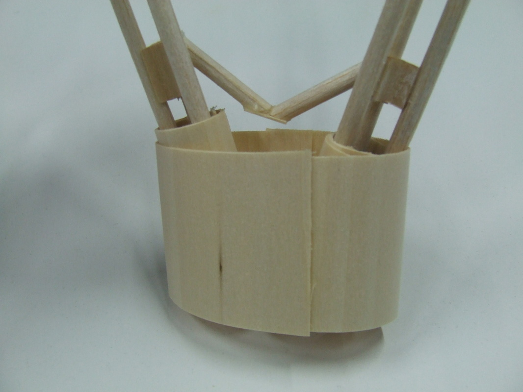
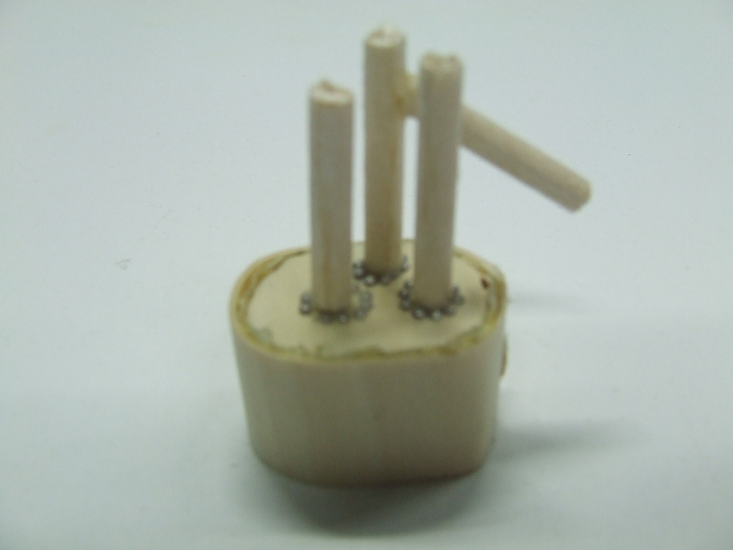
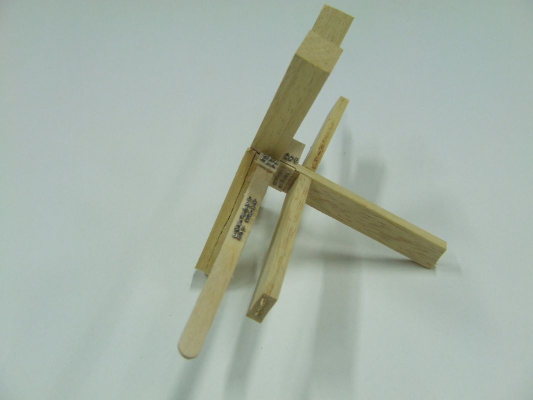
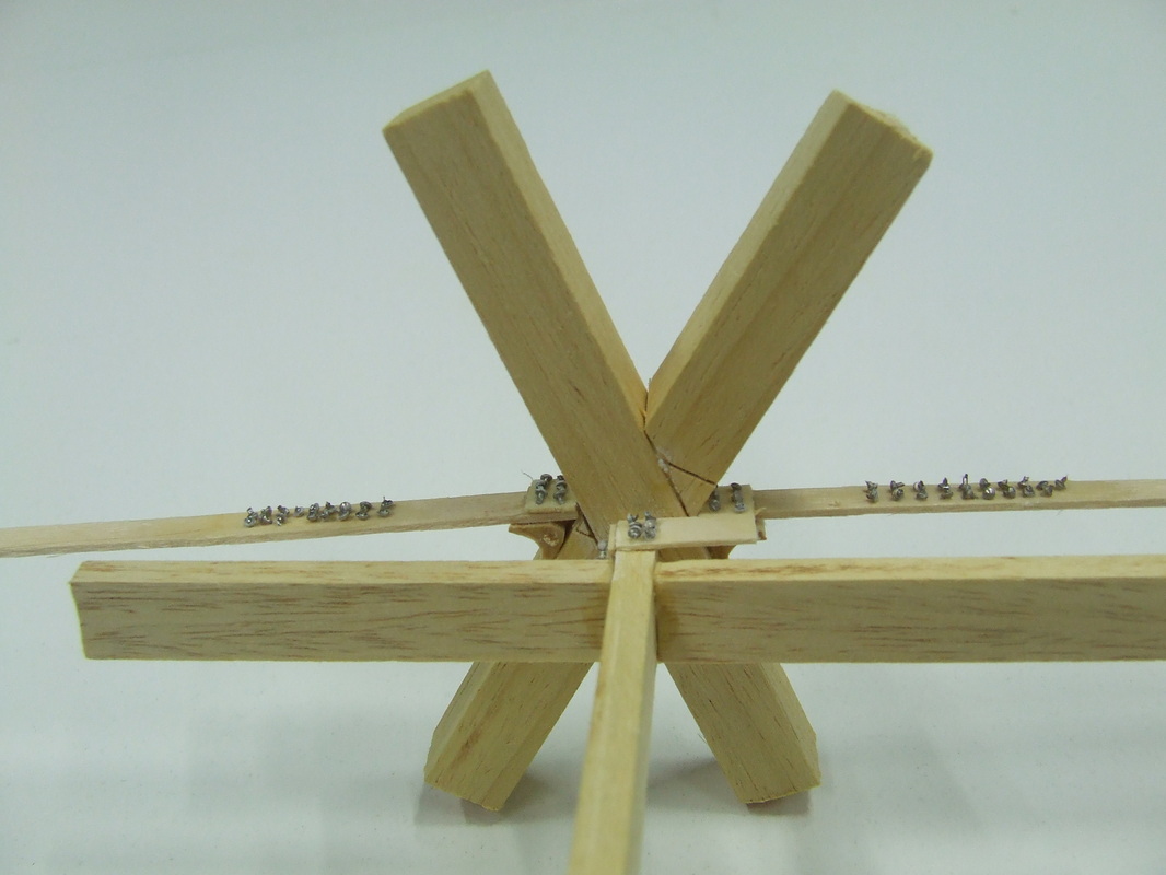
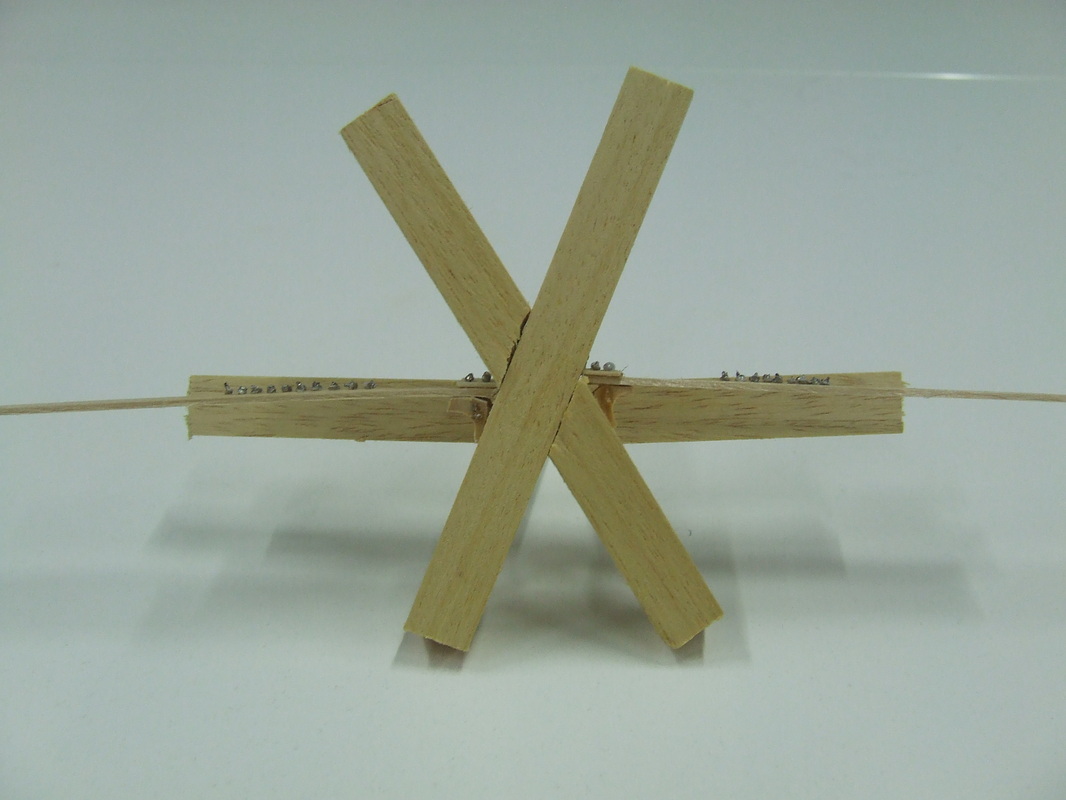
Photos of physical model
Capital gate tower in Abu Dhabi
Height: 525ft (160m)
Floors: 35
Building Use: Office and Hotel
Architect: RMJM ArchitectMechanical
Structural Type: Leaning TowerArchitectural
Style: DeconstructivismCost: $231 Million
Floors: 35
Building Use: Office and Hotel
Architect: RMJM ArchitectMechanical
Structural Type: Leaning TowerArchitectural
Style: DeconstructivismCost: $231 Million
Location: Abu Dhabi is the capital and the second largest city in the United Arab Emirates. Abu Dhabi lies on a T-shapedisland jutting into the Persian Gulf from the central western coast. The city proper, making up an area of67.340 km2 (26.000 sq mi), had an estimated population of 896,751 in 2009.
Reference:Wikipedia, Capital Gate, 2010
Reference:Wikipedia, Capital Gate, 2010
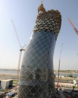
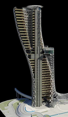
The 35-story asymmetric diagonal structure will stand on an extremely dense mesh of reinforced steel and to balance the gravitational, wind and seismic pressures caused by the lean, the tower has been drilled 30 meters below the ground surface. Leaning Westward 18 degrees, this structure is 4 times more inclined than the Leaning Tower of Pisa. Capital Gate will not only defy gravity but is set to be a benchmark for future leaning constructions around the globe .
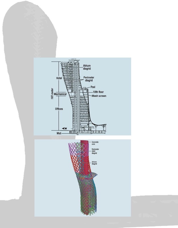
The gravitational pressure caused by the 18-degree incline is countered by the world’s first “pre-cambered core”; a technique that utilizes 15,000 cubic meters of concrete reinforced with 10,000 tons of steel with the core deliberately built slightly off-center.
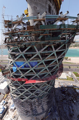
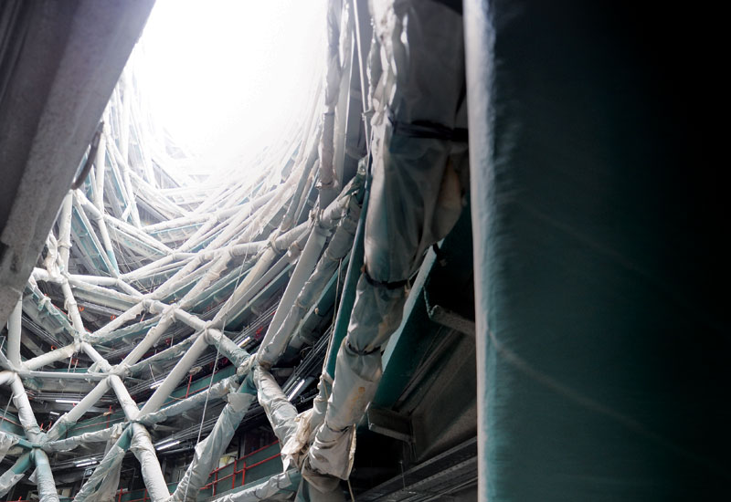
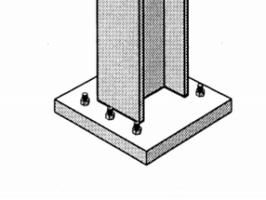
Capital Gate’s base structure is a vertical concrete core surrounded by a steel diagrid describing the external form of the tower. Steel beams span between the two, supporting metal deck and concrete composite floor slabs. Above the base, the atrium is formed with an internal steel diagrid attached to the core. . A diagrid exterior structure made of triangular tubular steel units creates a ridged mesh to add support and act as a frame for the custom glazing units. The exterior was also developed to reduce the supports mass, thus weight.
Reference:http://www.scribd.com
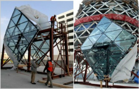
The tower is covered with 728 panels of glass cut to the size and shape of a diamond that due to the curvatureof the structure will be embedded in a slightly different angle.
Foundation: Due to the soil conditions and the building itself the foundation system used was a deep foundation. Thebuilding sits atop a dense mesh of reinforcing steel and concrete that connects a total of 490 piles (CapitalGate, 2010). To help counteract the large overturning moment, which is caused by the buildings lean, the pileswere two different sizes. Of the total 490 piles, 287 were 1m (40in) in diameter, and 20-30 meters (65-100 feet)deep, the remaining 193 piles had a diameter of 600mm (24 inches) with a depth of 20m (65 feet). Unlike mostbuildings, whose piles are in compression, the piles for Capital Gate are in tension. This was done to helpresist the upward forces that would tend to pull the pile out of the ground. The building, however, cannot sitdirectly on top of the piles. All 490 piles were capped together using a densely reinforced concrete mat footingof nearly 2 meters (7 feet) thick (Roberts, Lean on Me, 2010)
Reference:http://www.scribd.com
Reference:http://www.scribd.com
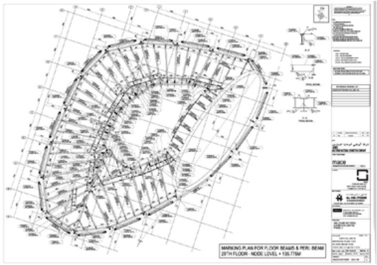
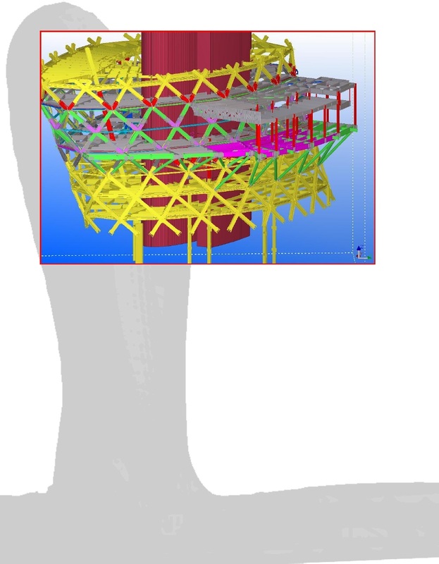

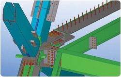
The external diagrid elements are made from welded steel plates. The internal diagrid around the atrium is made of round steel profiles. The diagrid connections are nodes located at the floor slab levels where girders frame in. The external diagrid nodes are also designed for the façade panels to frame on the outside. The diagrid connections are nodes located at the floor slab levels where girders frame in. The external diagrid nodes are also designed for the façade panels to frame on the outside. Designers studied these connection details extensively to optimize construction, as well as structural integrity.
Reference:http://www.scribd.com
Reference:http://www.scribd.com
Photos of physical model
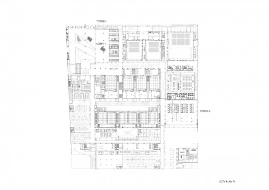
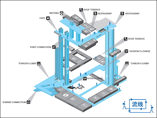
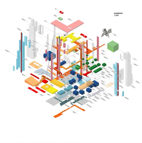
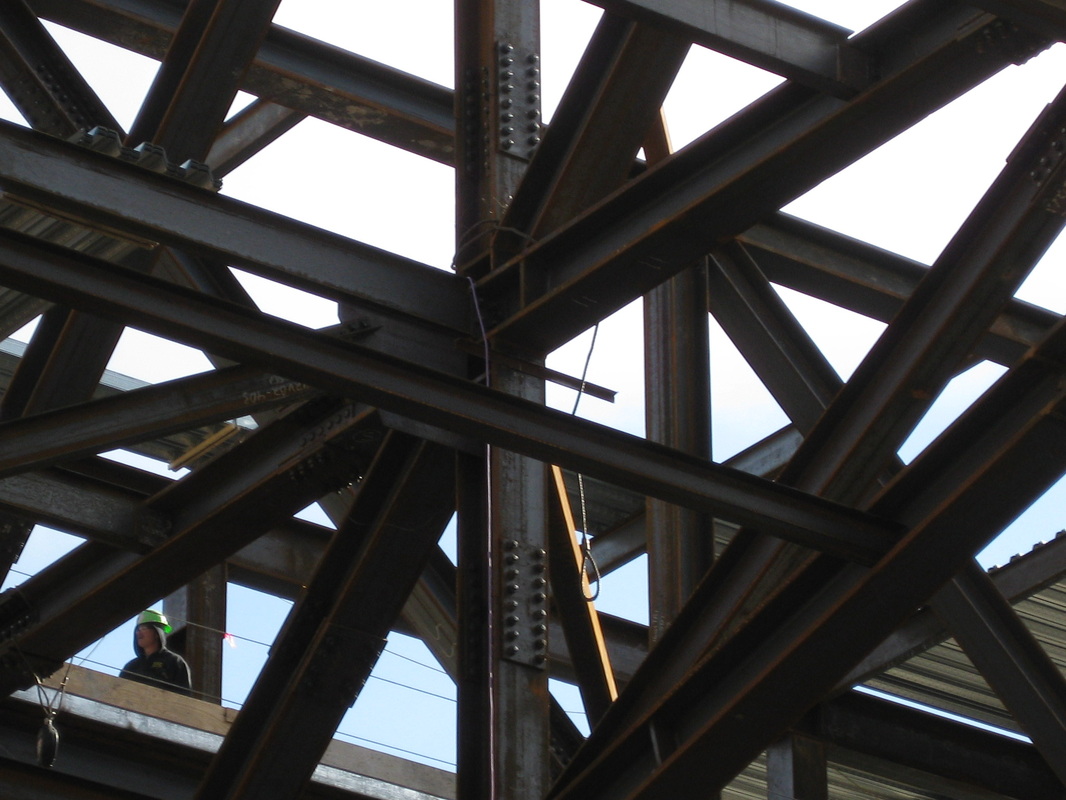
CCTV building in Beijing
A diagrid 'exoskeleton' system was adopted on the external faces of the building to give a tube structure that resists gravity and other lateral forces. The positioning of the columns and diagonal tubes reflects the distribution of forces in the surface skin of the building.The
columns of the diagrid have the same exposed width, but the depth varies
according to the load, while the diagonals are
plate girders, with only the steel thickness varying. A butterfly plate
links perimeter columns, braces and beams. The irregular geometry of steel
structure facade gives it stability to cope with different load conditions. The
facades of CCTV portray the irregular geometry of the building’s steel
structure. Its sometimes dense, sometimes more open grid of diagonals forms the
stability system of the building and reflects the distribution of forces that
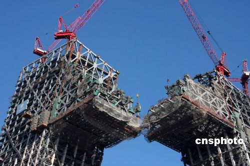
the structure experiences under different load conditions. The vertical core structure was generally erected three storeys ahead
of the perimeter frame.
|
|
This meant that the perimeter columns could be initially bolted in place and braced to the core columns with temporary stays, then released from the tower crane before final surveying and positioning.
|
|
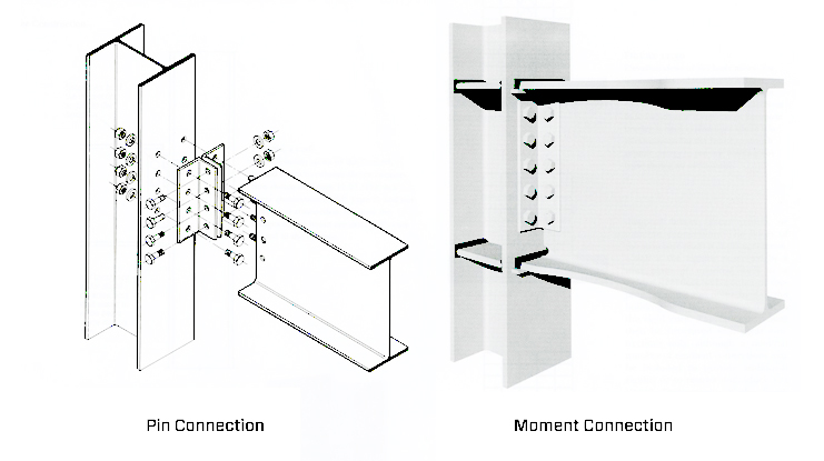
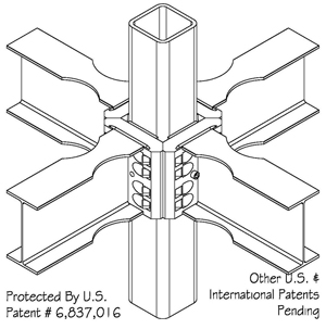
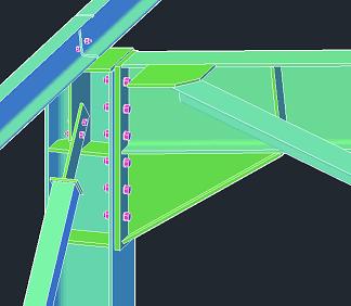
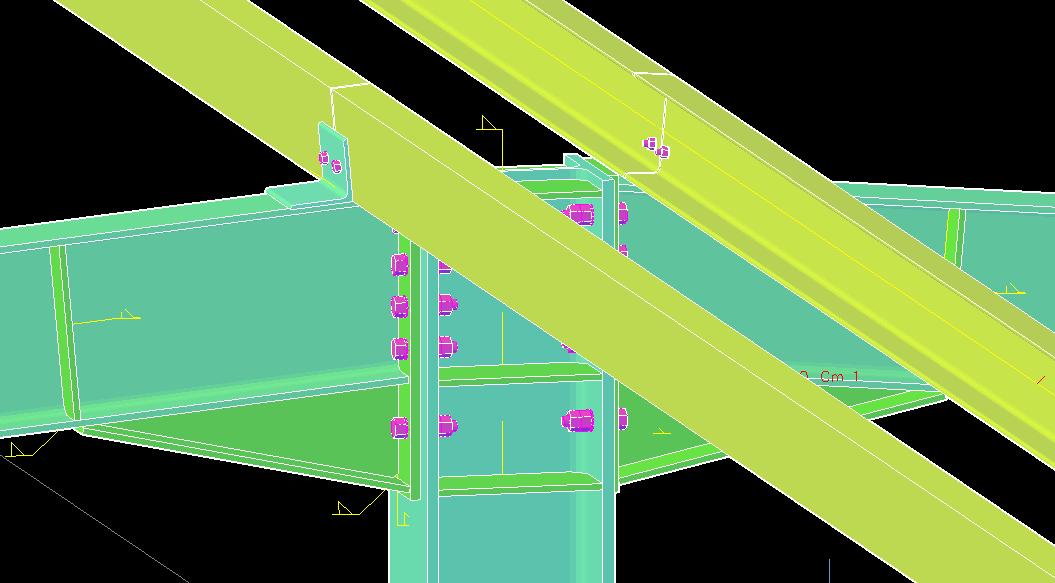
The force from the braces and edge-beams must be transferred through and into the column sections with minimal disruption to the stresses already present in the column. The connection is formed by replacing the flanges of the steel column with large ‘butterfly’ plates, which pass through the face of the column and then connect with the braces and the edge-beams. No connection is made to the web of the column to simplify the detailing and construction of the concrete around the steel section.
The joints are re q u i red to behave with the braces, beams, and columns as ‘ strong joint/weak component’. The connections must resist the maximum probable load delivered to them from the braces with minimal yielding and a relatively low
degree of stress concentration.Transfer trusses support these additional columns, spanning between the internal core and the external tube structure.
Reference:http://www.designbuild-network.com
degree of stress concentration.Transfer trusses support these additional columns, spanning between the internal core and the external tube structure.
Reference:http://www.designbuild-network.com
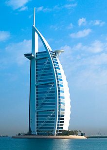
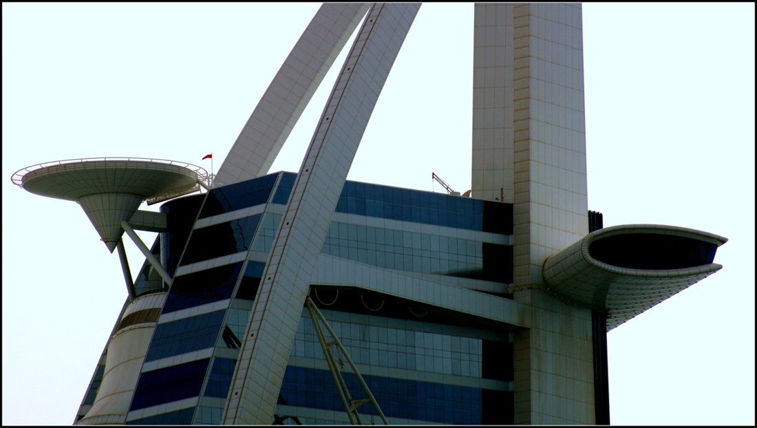
Burj Al Arab
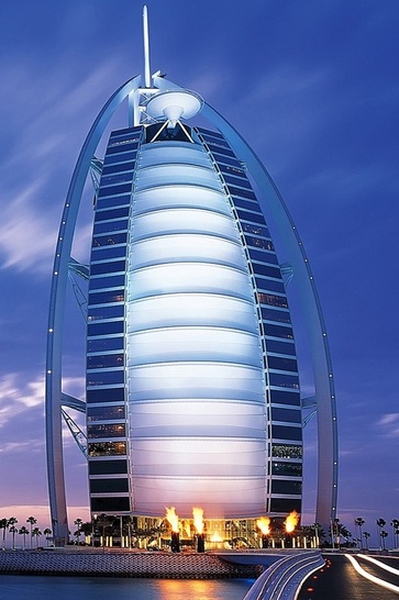
Burj Al Arab is a luxury hotel located in Dubai, United Arab Emirates. At 321 m (1,053 ft), it is the fourth tallest hotel in the world. Burj Al Arab stands on an artificial island 280 m (920 ft) from Jumeirah beach and is connected to the mainland by a private curving bridge. The shape of the structure is designed to mimic the sail of a ship.
Sometimes referred to as "the world's only seven-Star hotel", its star rating is disputed.
Sometimes referred to as "the world's only seven-Star hotel", its star rating is disputed.
- Architect Tom Wright of Atkins
- Construction started 1994
- Completed 1999
- Opening December 1999
- Cost USD $ 650 million
Reference: Wikipedia
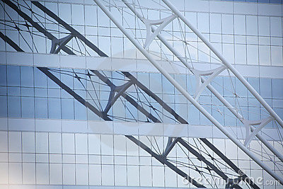
A term to describe the cross-braced frame;a building technique used to provide a structure support and prevent sliding.
Pair of diagonal steel trusses rising 273m above ground.
Provide the structure horizontal stability in all directions.
Each steel truss weighs 165 ton each and total weigh is about 2800 tons.
Pair of diagonal steel trusses rising 273m above ground.
Provide the structure horizontal stability in all directions.
Each steel truss weighs 165 ton each and total weigh is about 2800 tons.
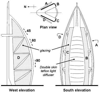
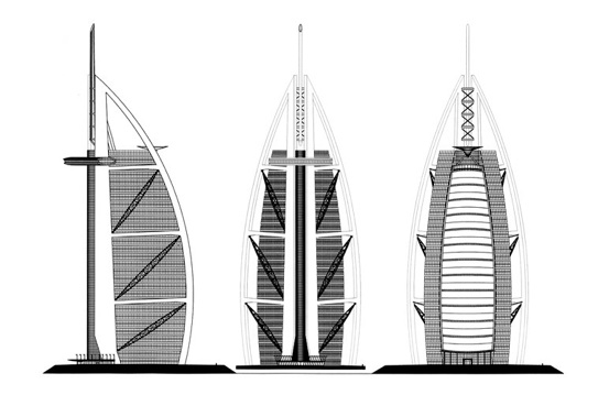
Rear brace frame-This brace ties both the cores together to give stability to the structure.The shape of the Rear Brace is similar to ‚X‘ are erected in segments.Diagonals-The diagonals connects with a 300mm diameter pin connection to the core wall and the Rear-leg structure.
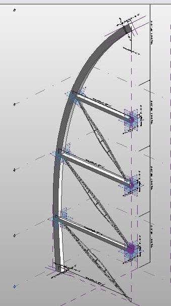
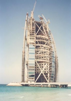
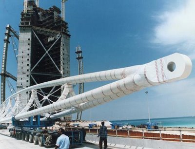
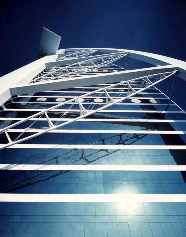
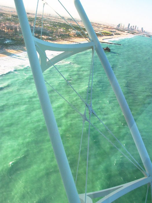
The exoskeleton is mede up of two legs on both sides of the building starting from the ground level to 273 metres and connected to the front legs.
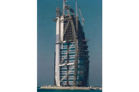
Sky Restaurant Structure
The 350 ton structural steel sky Restaurant was one of the most complex and potentially dangerous structures to erect. The box girders cantileve out for about 30m from the main core wall of the building connected to about 200 tons of embedment. The
restaurant is having a floor size of 70m x 25m. The total structure is built up on eight cantilevered box sections and two end trusses at 200m above the ground level. The beauty of the restaurant is that it over looks the sea. One of the highlights is, two 30m long girders had to be erected at 200m level but the crane did not have the lifting capacity so we had to split the girders into halves and joint up in the air with full penetration welding, it was a real challenge and Eversendai took it up and performed beyond everyone’s expectation in a record duration of 40 days.
Reference: http://www.mbam.org.my/mbam/images/MBJ3Q06%28pdf%29/@BurjAlArb.pdf
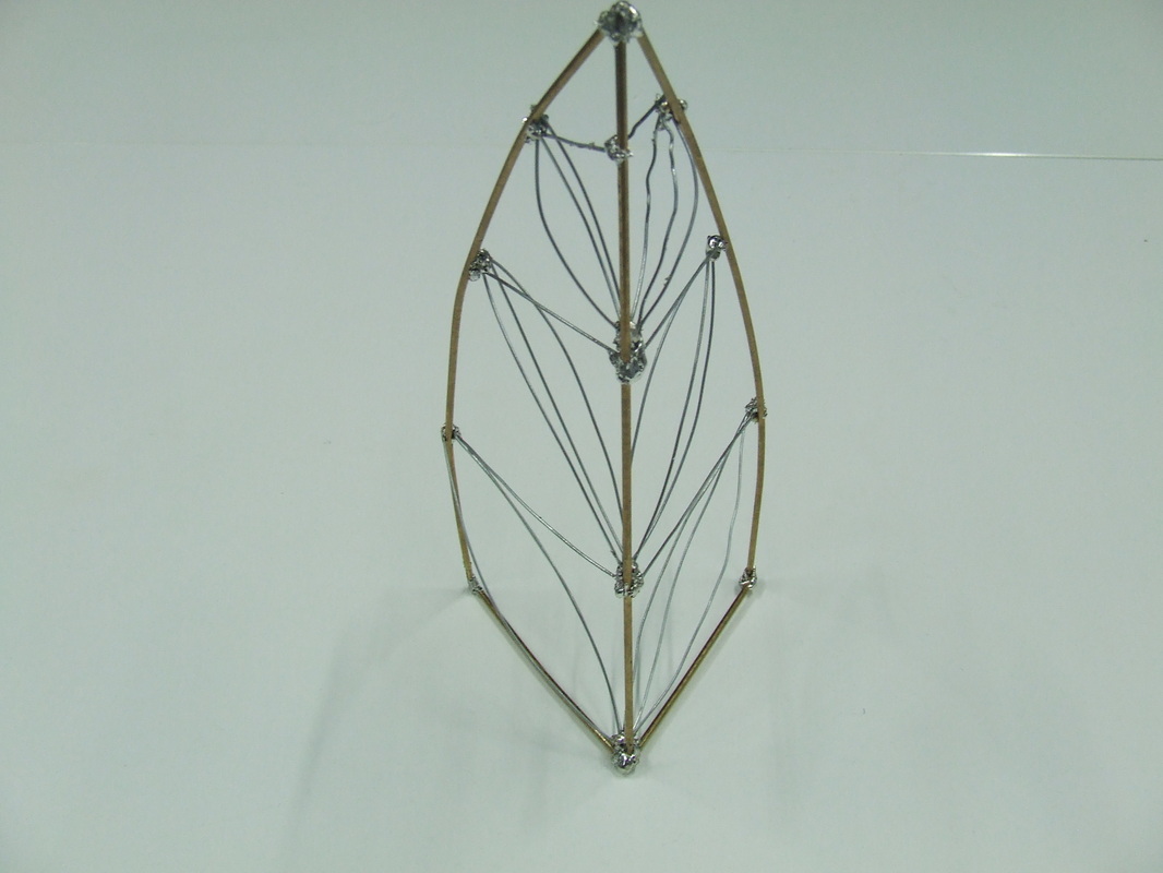
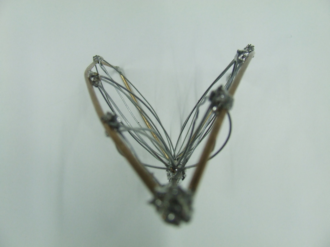
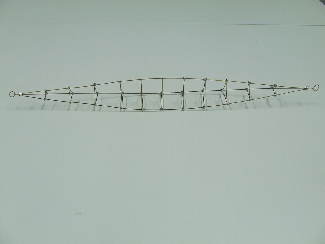
Photos of physical model
PART TWO/ WEEK 2: Design Development
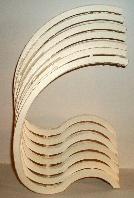
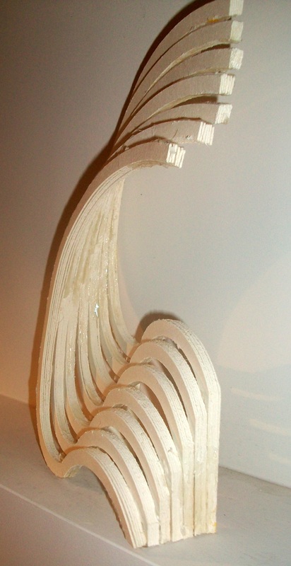
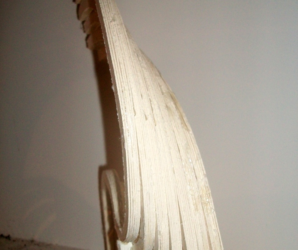
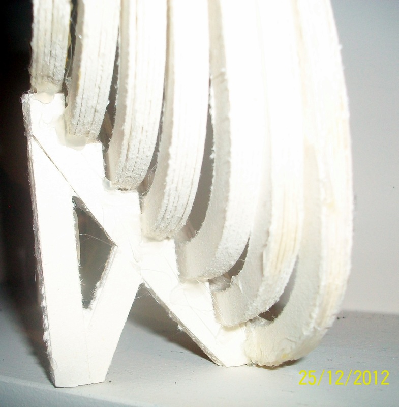
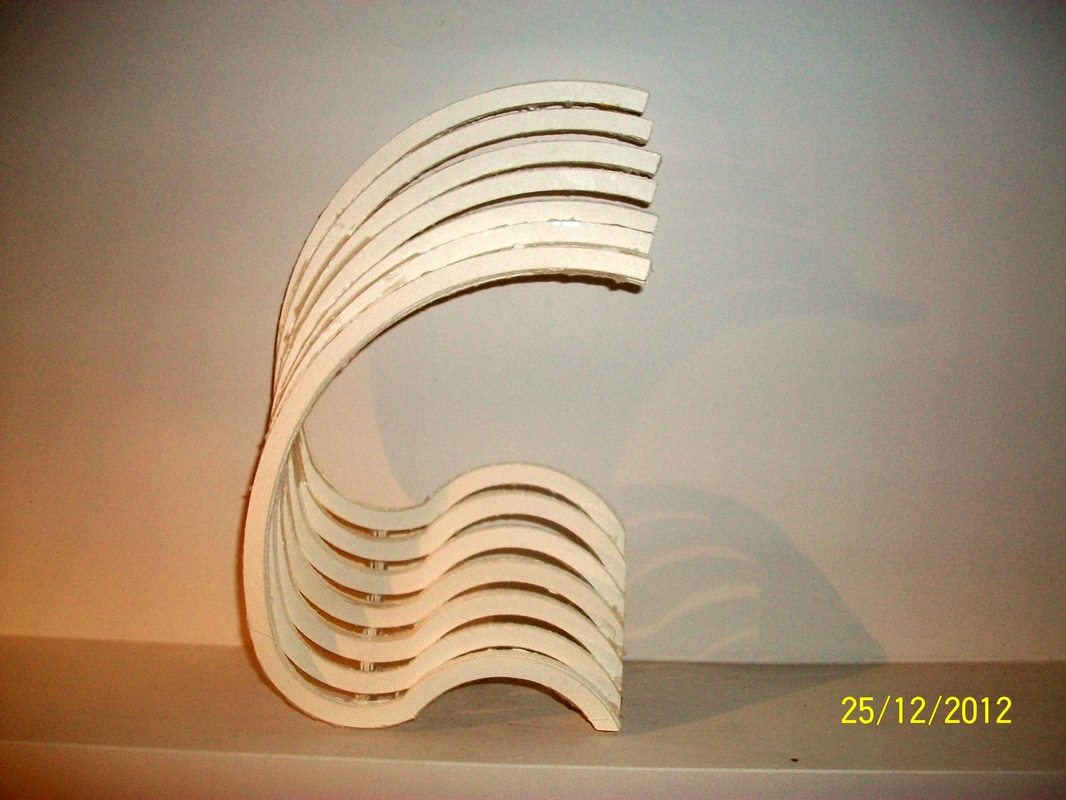
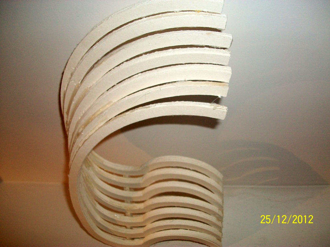
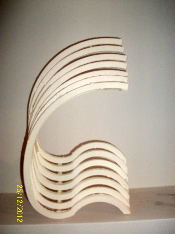
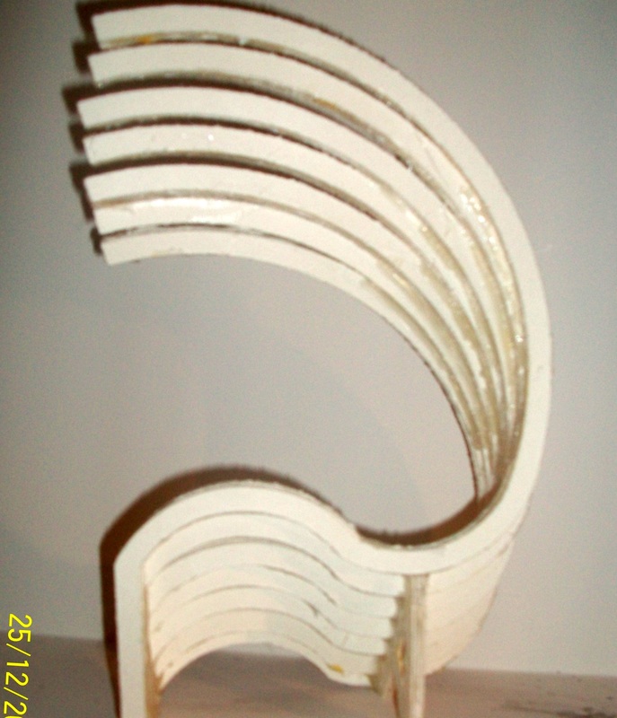
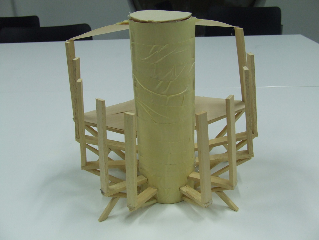
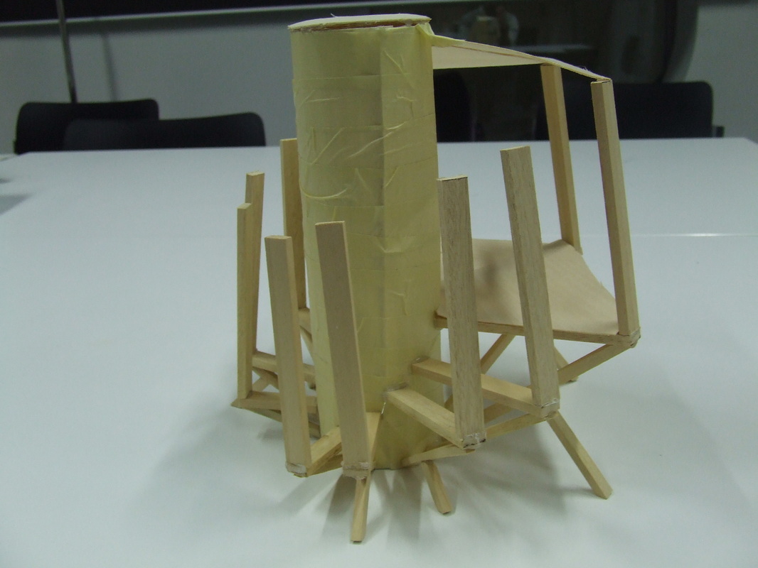
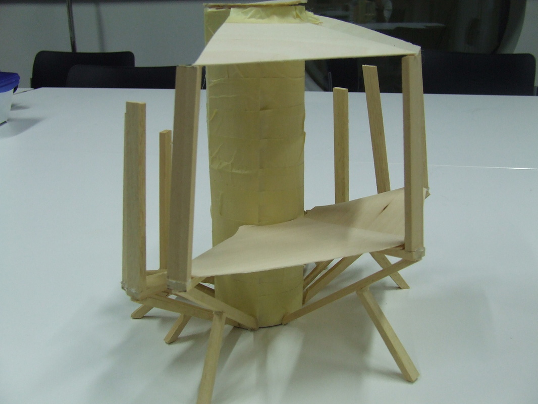
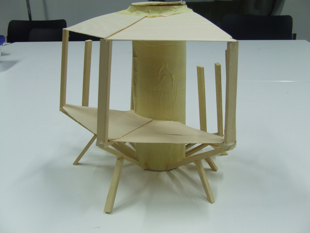
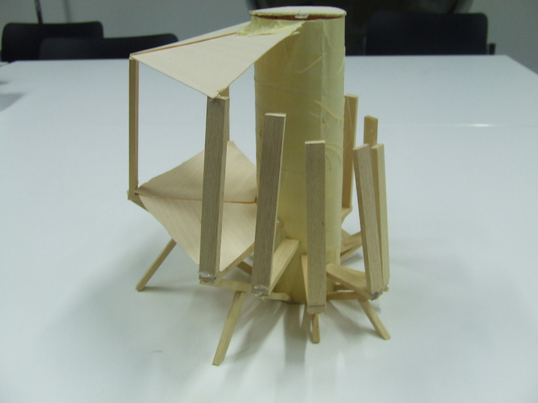
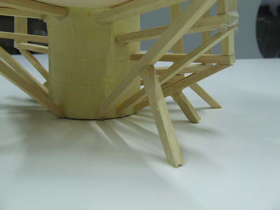
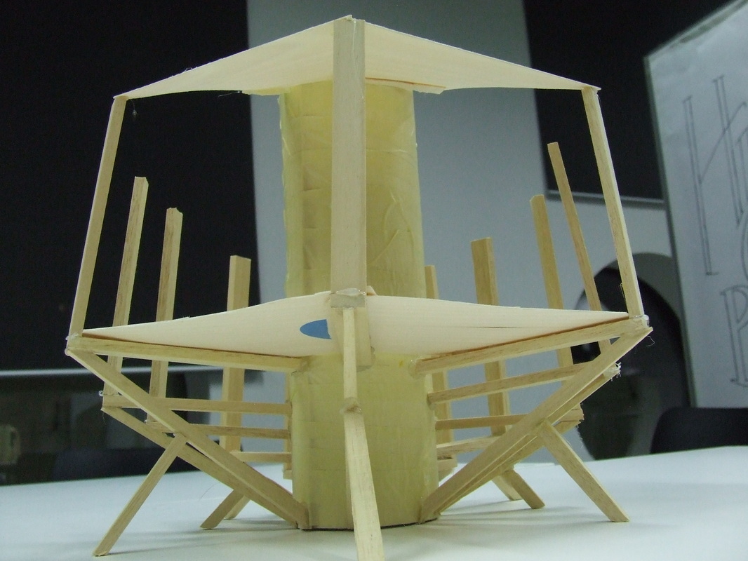
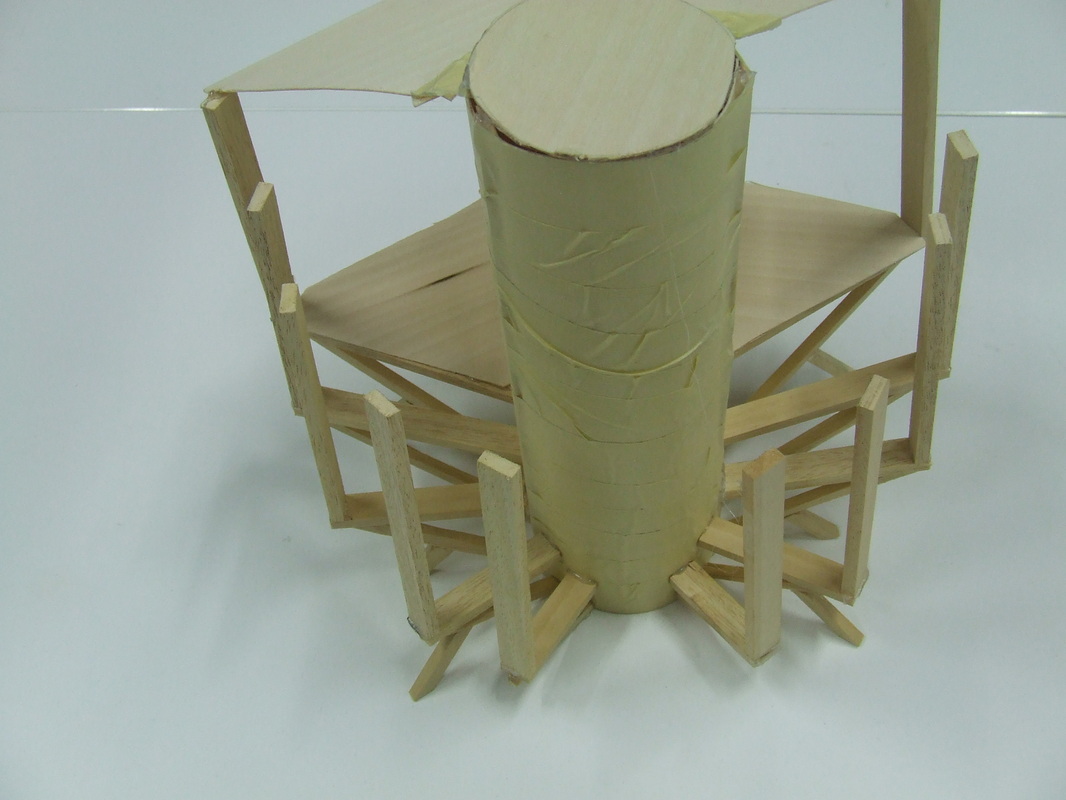
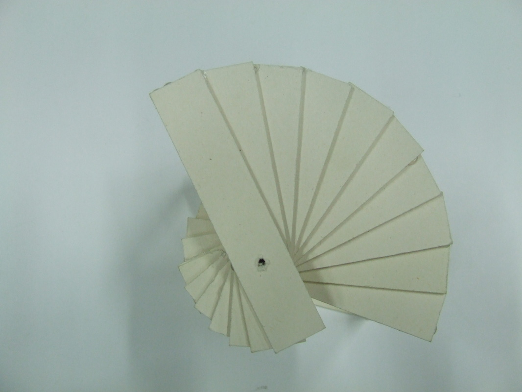
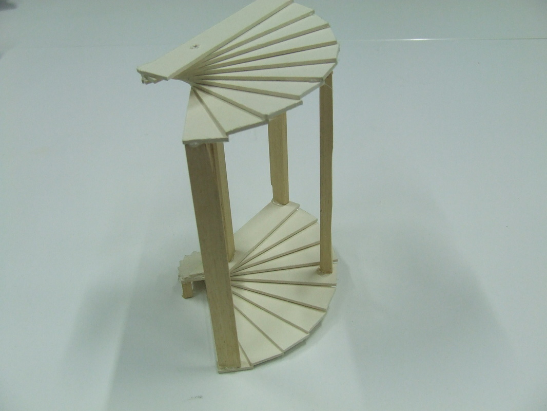
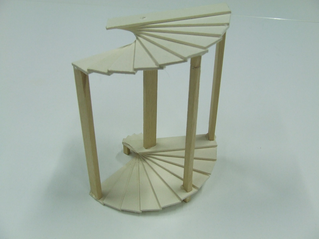
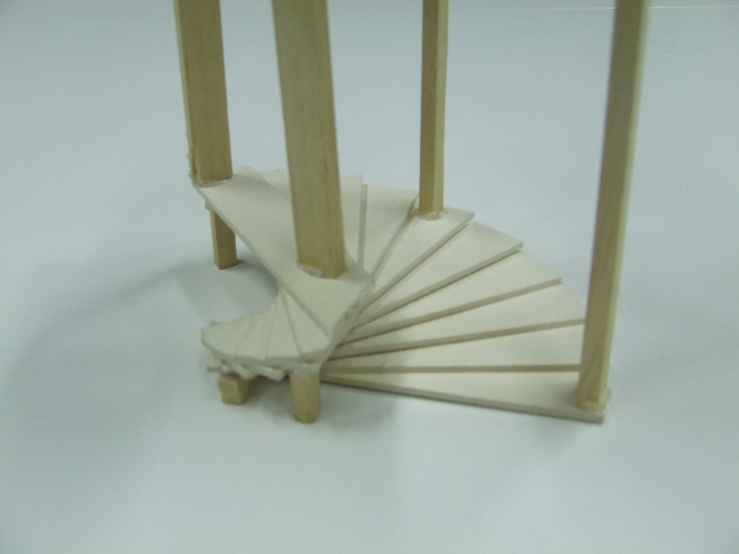
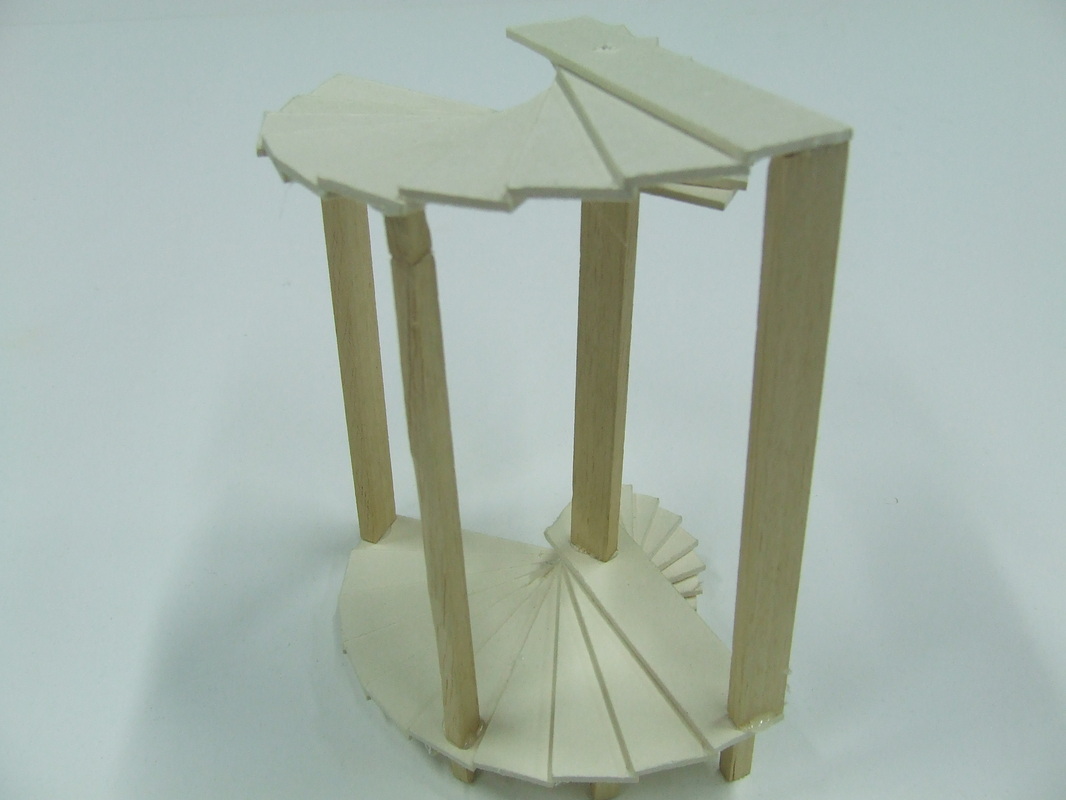
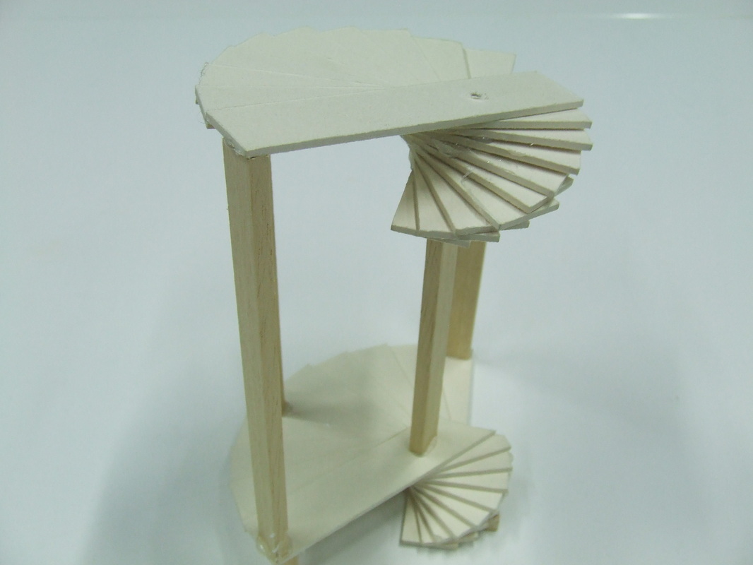
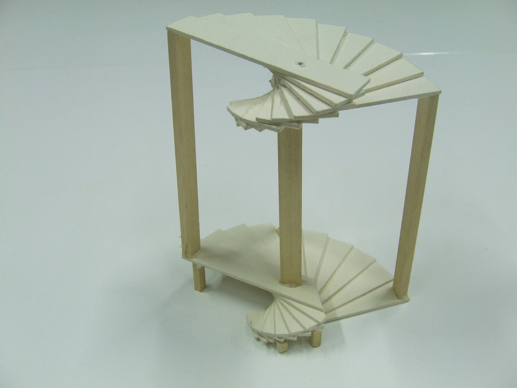
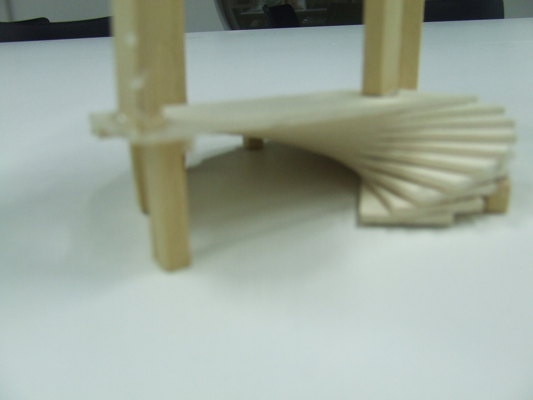
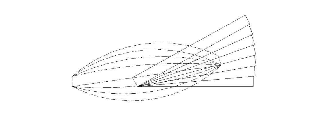
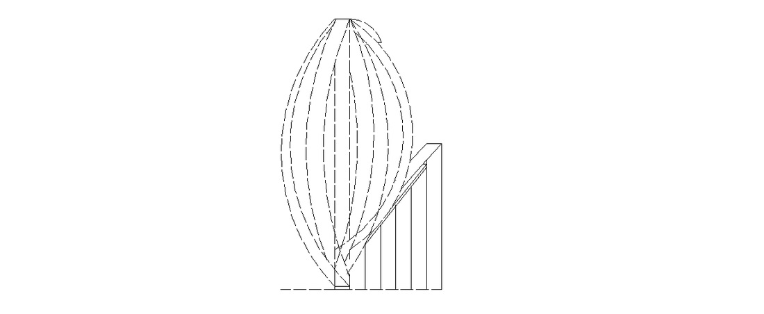
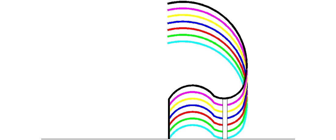
First idea
This is freestanding wood structure. There are five stairs at the two sides which takes you to the main platform which is 1.5 m of the ground. Every one of the steps is with same width ( 20 sm ) but with different lengh which depends of the high and has support to the ground for more stability. Everything is hold on the pillar in the middle.
Photos of physical model
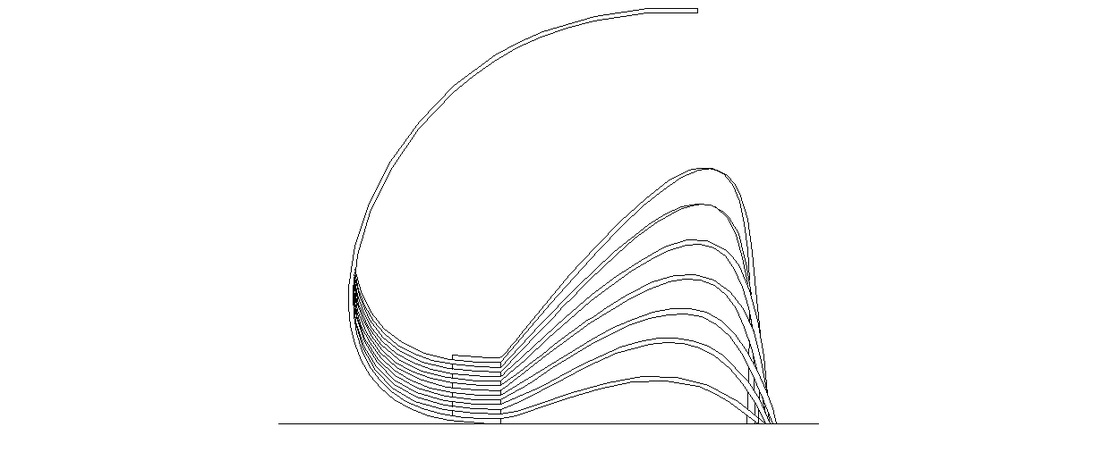
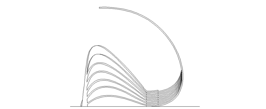
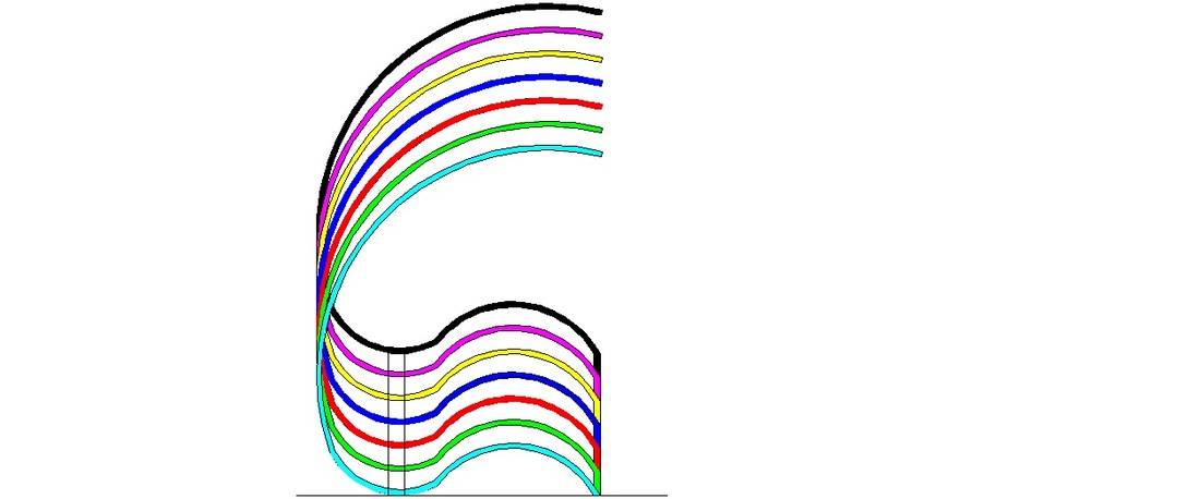
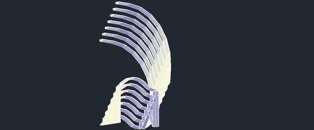
Second idea
Group idea
Group:
- Lavanya Kumaran
- Lucien Abou-zeid
- Dimitar Dimitrov
- Christianne Saitine-Nkele


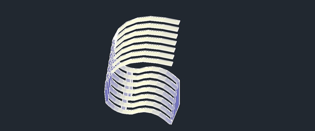

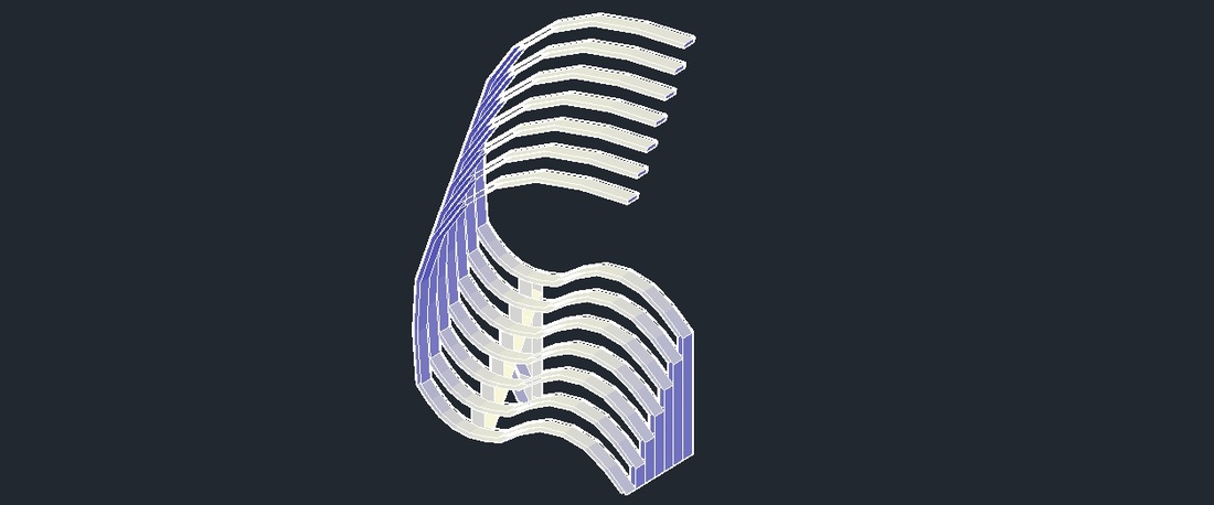
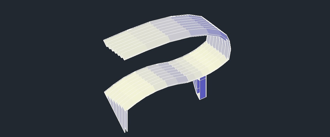


Photos of physical model